Custom molded fiber packaging is often commissioned from a product photo, a rough drawing or an existing plastic tray. Yet a geometry that looks convincing in CAD may not release from a forming mold, dry uniformly, stack reliably or protect its contents. The difficult stage is not drawing the shape. It is converting a product requirement into manufacturable tooling, measurable acceptance criteria and stable production output.
Short answer. Define the use conditions and critical finished-part dimensions, then test a representative prototype. Approve the tooling after a trial on the intended production line demonstrates fit, function and repeatable accepted output under recorded conditions.
The tooling brief covers custom molded pulp and bagasse parts such as protective inserts, trays and selected foodservice items. For background on materials and uses, see the molded fiber packaging primer.
What the drawing must explain before tooling begins
The customer’s initial file rarely captures all the functions of a package. A protective insert needs controlled contact points, clearance around sensitive components and an acceptable response to shocks and stacking loads. A food tray may need dimensional stability after moisture and temperature exposure, food-contact documentation and a compatible lid or lidding film.
A minimum design input should define:
- Protected product or food: external dimensions, mass, contact locations, vulnerable surfaces, and temperature or moisture exposure.
- Pack-out architecture: part orientation, insertion and removal method, surrounding carton, lid, film or accessory, and intended stack height.
- Loading conditions: handling, warehousing, transport vibration and drops for industrial inserts; fill weight, holding and distribution conditions for foodservice parts.
- Target geometry: envelope dimensions, clearances, draft/release requirements, nesting or denesting constraints and critical interfaces.
- Material system: pulp type or blend, additives, coatings or films, color and surface-finish expectations.
- Commercial scope: forecast volume, number of cavities, line capability, tool ownership, engineering changes and definition of an accepted part.
When these inputs are absent, mold design becomes a guessing exercise. Two buyers might request the same outside dimensions while needing completely different wall profiles because the product load, protective function and pack-line requirements differ.
Translate performance needs into fiber geometry
Contact points and clearances come first
For a protective insert, identify where the package should touch the product and where it must not. The design can then use ribs, support islands, arches or crush zones to control the load path. These shapes are functional; they should not be added simply to make the tray appear engineered.
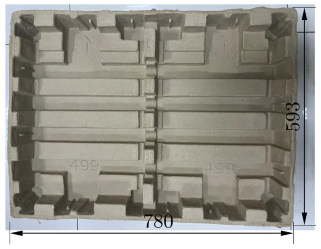
Zhihang Li and Kuanmin Mao modeled how wall thickness, draft angle and cell dimensions affect normal stiffness in a specific molded-pulp structure. That gives designers a basis for deciding which features to prototype and measure under the intended product load. The study’s dimensions and material inputs belong to the modeled specimens. [M1]
Formability is different from visual fidelity
Deep pockets, abrupt transitions, very narrow ribs and difficult undercuts can be challenging to form or release. The actual result depends on mold construction, fiber distribution, dewatering, pressing, drying and the chosen manufacturing route. A CAD model may show crisp corners that a real fiber preform cannot reproduce consistently.
Mattia Didone and Guido Tosello studied dewatering, replication of small features and internal structure in pulp thermoforming. The choice of pulp affected how faithfully the tool reproduced small features in their tests. A later addendum explains how they defined cycle time, selected specimens for void analysis and distinguished the equipment setpoint from the estimated mold surface temperature. Before a tooling trial, agree on where the converter measures temperature and which steps it counts in the cycle. [M2] [M3]
Design for stacking and release
Packaging that nests too tightly may jam during automated denesting; packaging that does not nest efficiently can waste shipping space. A part can also stick during mold release or deform as it dries. Tooling design therefore needs to consider draft, contact area, possible venting or drainage paths, and how a finished part will move through downstream handling. These are engineering questions to resolve in trials, not fixed angle or wall-thickness rules that apply to every molded-fiber process.
For food trays, rim flatness and consistency can be more important than a beautifully embossed base. A lidding-film or snap-fit concept should be tested on production-like parts, not on an ideal CAD perimeter.
What a production mold actually has to control
In wet forming, fibers collect on the forming surface as water is drawn away. Forming and transfer surfaces, drainage or vacuum, matched heated tools where used, release and trimming all influence the finished part. Confirm the planned wet or dry forming route and its pressing and drying steps before specifying the tool.
Bioleader, a manufacturer with a commercial relationship with Degradable Packaging, describes a custom molded fiber development process that can start with a drawing or physical sample. The company reports reviewing the design and making prototypes before developing production molds, then moving to forming and inspection for volume production.
Didone and colleagues survey molded-pulp manufacturing routes in their 2017 review. In a separate 2020 study, Prateek Saxena and colleagues describe tooling routes that include metal additive manufacturing. Their public abstract establishes the approach they investigated. A commercial comparison still needs a quote and output data for the specified part, tool life and line. [M4] [M5]
For each new part, the converter and toolmaker should agree which surfaces control critical dimensions and which process operations may change them. It is particularly risky to sign off only the metal tool while leaving finished-part shrinkage, warpage, trimming and moisture conditioning outside the acceptance criteria.
Prototype, pilot tool and production tool are different commitments
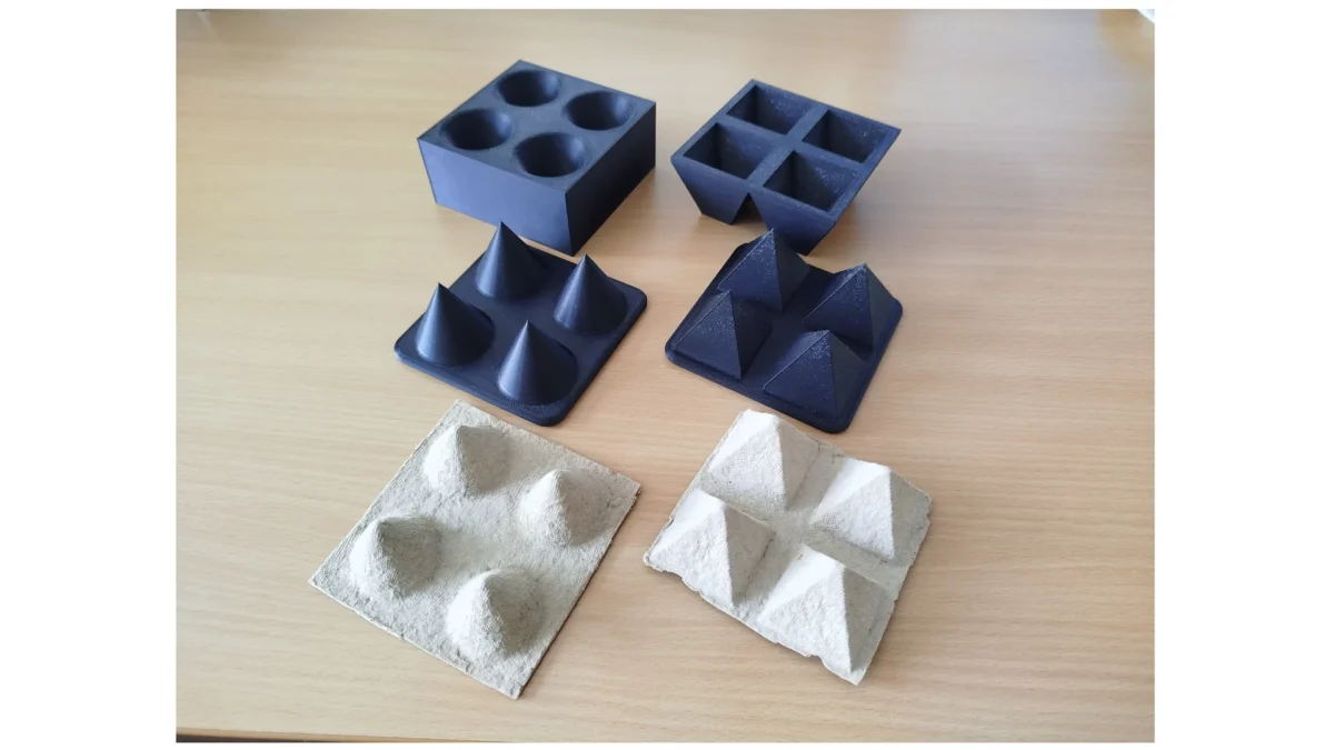
Claude Humbert and colleagues used 3D-printed PLA molds to hand-form cones and pyramids for a preliminary cushioning study. A prototype of this kind can help a team select a geometry for further testing. The trial on the intended line then shows how the selected fiber, tooling and finishing steps affect repeatability. [M6]
| Development gate | Decision being made | Minimum useful evidence | Evidence still needed |
|---|---|---|---|
| Concept feasibility | Is the geometry and process route plausible? | Brief, initial drawing, material/process assumptions | Representative sample, fit and initial function |
| Representative prototype | Does the part fit and perform in a first trial? | Physical samples, revised drawing, observed defects, basic function tests | Repeatable finished parts from the intended line |
| Tooling/process trial | Can the selected tool and line repeatedly make acceptable parts? | Setup record, measurements, rejects, cycle and finishing observations | Evidence that accepted output holds at the planned schedule |
| Production acceptance | Is the released part ready for controlled orders? | Approved drawing, lot traceability, agreed tests, accepted-part output, change-control record | Ongoing lot checks and requalification after relevant changes |
Use the four decisions to agree what each sample needs to demonstrate. A simple protective spacer may require a shorter trial than a sealed food tray. A visually simple insert may need more testing if its failure could damage an expensive product.
Build a measurement plan around the failure mechanism
It is easy to measure a part that already looks good. Useful qualification targets the failure modes that would actually matter during storage, handling or consumption.
Protective packaging: test the packed system
Use individual insert tests to screen candidate geometries. Assess transport performance on the finished packed assembly with the actual product load, orientation and outer carton. Select fit, stacking, handling, drop and vibration tests to match the expected distribution conditions.
Record package orientation, specimen conditioning, mass, test sequence, visible damage and product condition. Recheck the relevance of the result when the product weight, support points or carton geometry changes.
Foodservice packaging: distinguish structural, barrier and compliance tests
For trays and containers, separate wall and rim stability, leakage, grease resistance, temperature exposure and food-contact suitability. Coatings or additives may be necessary for some applications, but they change the finished construction being evaluated.
In laboratory tests, Supattra Klayya and colleagues reported improved water and oil resistance with an ethyl cellulose coating on bowls formed from kraft paper sheets. Their construction used hot-pressed sheets and a dip-applied coating. Define a separate performance test for the finished bagasse tray, including its actual fiber and barrier construction. [M7]
For intended food contact, document the finished construction, the destination market, the food type and the expected contact time and temperature. Keep supplier declarations and relevant compliance evidence with the specification. See the related analysis of bagasse tray and lid tests for grease resistance, seals and recovery.
Dimensional control: inspect after conditioning and finishing
A mold can reproduce its own shape well while the product changes dimensions during drying, trimming or storage. Measure critical features on the article at an agreed conditioning point. Record which dimensions govern product fit, lid engagement, denesting or automated pick-and-place; not every visual contour needs the same tolerance.
Record the number of independent parts measured and report the spread by cavity and sampling point where relevant. A few pulls from the best cavity can conceal variation elsewhere in the tool. Agree how to sample across the intended run and which dimensions and defects decide acceptance.
Compare custom tooling proposals on accepted output
“Tool cost” is an incomplete economic comparison. A low initial price can become expensive when the tool requires repeated adjustments, frequent cleaning, slow drying or high scrap rates. A more useful commercial analysis separates one-time engineering and tooling costs from the recurring cost of acceptable parts.
Compare lots using an agreed cost boundary.
Indicative cost per accepted part = total attributable lot cost ÷ number of parts that pass the agreed checks.
Include materials, processing, finishing, inspection, setup and the share of tooling cost allocated to the lot. Count reject handling, disposal or rework only to the extent that it adds cost beyond those items. For illustration, a $600 lot costs $0.60 per accepted part at 1,000 accepted units and about $0.67 at 900 accepted units. Compare proposals at the same performance requirement, cost boundary and tooling allocation basis.
Ask whether the price includes design revisions, sampling, mold maintenance, ownership, replacement cavities, trimming dies and process development. Clarify what triggers additional engineering charges and how a rejected pilot trial will be handled. These questions may matter more than a small difference in the initial mold quote.
A hypothetical design choice: protective insert or food tray?
Consider a team designing an insert for an electronic component shipped in a corrugated carton and a team designing a shallow takeaway tray for warm, greasy food. These are hypothetical examples.
For the insert, prioritize controlled contact, crush response, fit and protection of the packed product. For the food tray, verify dimensional stability with the intended food, barrier performance where needed, food-contact suitability for the intended use and compatibility with any lid or film. Set the geometry and test plan around those different requirements.
For the insert, define acceptable product condition after distribution testing. For the tray, specify the food exposure, barrier and lid performance to verify. Document any recovery or compostability claim for the finished construction and intended recovery route.
Seven checks before approving a production mold
- Is the finished-part drawing version-controlled? Specify critical dimensions, surfaces, interfaces and an agreed conditioning state.
- Is the forming route identified? Confirm whether the project uses wet molding, wet thermoforming or a distinct dry-forming route; the same word “molded” does not define the process.
- Is the fiber and additive formulation documented? Define what changes require requalification.
- Has the relevant application been tested? Evaluate the actual product or food and the intended downstream pack-out.
- Are sampling and acceptance criteria written down? Agree on defect categories, dimensional limits, functional checks and lot traceability.
- Is commercial output measured as accepted parts? Keep setup time, rejects and finishing in the cost and capacity assessment.
- Are claims and responsibilities separated? Tooling acceptance does not itself establish food-contact authorization, recycling acceptance, compostability or whole-life environmental superiority.
Release the tool when the approved drawing, material and production process repeatedly deliver parts that meet the documented use. Attach the sampling results and acceptance criteria to the tool sign-off so the next run can be judged on the same basis.
Sources / References
- [M1] Li and Mao (2026), Simplified Dynamic Modeling of Molded Pulp Packaging for Road Transportation. DOI 10.3390/app16021090.
- [M2] Didone and Tosello (2019), Moulded pulp products manufacturing with thermoforming. DOI 10.1002/pts.2412.
- [M3] Didone and Tosello (2021), Addendum to Moulded pulp products manufacturing with thermoforming. DOI 10.1002/pts.2543.
- [M4] Didone et al. (2017), Moulded Pulp Manufacturing. DOI 10.1002/pts.2289.
- [M5] Saxena et al. (2020), Mold design and fabrication for thermoformed paper-based packaging. DOI 10.1016/j.jmapro.2020.07.029.
- [M6] Humbert, Jadeau-Guichard and Nicolay (2024), Prototyping molded-pulp protection pads. DOI 10.3390/app142411516.
- [M7] Klayya et al. (2026), Ethyl cellulose coating for molded kraft paper bowls. DOI 10.1021/acsomega.6c05004.
Found an error? Read our corrections policy and contact the editors.